10. Electric Current and its Effects

Textbook Exercises
Section outline
-
-
Q1. Draw in your notebook the symbols to represent the following components of electrical circuits:
Ans:
- Connecting wires:

- Switch in the ‘OFF’ position:

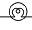
- Bulb:
- Cell:

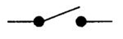
- Switch in the ‘ON’ position:
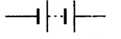
- Battery:
Q2. Draw the circuit diagram to represent the circuit shown in Fig.10.21.
Ans:

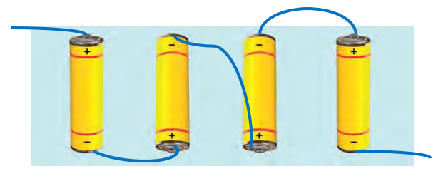
Q3. Fig.10.22 shows four cells fixed on a board. Draw lines to indicate how you will connect their terminals with wires to make a battery of four cells.
Ans:
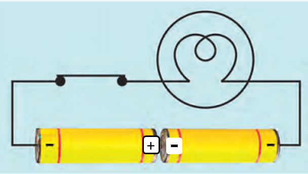
Q4. The bulb in the circuit shown in Fig.10.23 does not glow. Can you identify the problem? Make necessary changes in the circuit to make the bulb glow.
Ans:
- The bulb in the circuit is not glowing because the cells are not connected correctly.
- To make the bulbs glow, negative of one cell should be connected to the positive of another cell.
Corrected diagram is:
Q5. Name any two effects of electric current.
Ans:
The two effects of electric current are:
- Heating effect of electric current.
- Magnetic effect of electric current.
Q6. When the current is switched on through a wire, a compass needle kept nearby gets deflected from its north-south position. Explain.
Ans:
- When a current is switched on through the wire, the wire acts like a magnet.
- This is called magnetic effect of electric current.
- So, when a compass needle is kept near this wire, it gets influeced by the magnetic field around the wire.
- Hence, it is deflected from its north-south position.
Q7. Will the compass needle show deflection when the switch in the circuit shown by Fig.10.24 is closed?
Ans:
- The given figure, has no current source.
- Hence, even if the witch in the circuit is closed, there will be no electric current.
- So, the wire will not behave like a magnet in absence of current & the needle will not deflect.
Q8. Fill in the blanks:
Ans:
(a) Longer line in the symbol for a cell represents its positive terminal.
(b) The combination of two or more cells is called a battery.
(c) When current is switched ‘on’ in a room heater, it produces heat.
(d) The safety device based on the heating effect of electric current is called a fuse.
Q9. Mark ‘T’ if the statement is true and ‘F’ if it is false:
Ans:
(a) To make a battery of two cells, the negative terminal of one cell is connected to the negative terminal of the other cell. = F
(The negative terminal of one cell should be connected to the positive terminal of another cell.)
(b) When the electric current through the fuse exceeds a certain limit, the fuse wire melts and breaks. = T
(c) An electromagnet does not attract a piece of iron. = F
(A electromagnet acts like a magnet when current passes through it)
(d) An electric bell has an electromagnet. = T
Q10. Do you think an electromagnet can be used for separating plastic bags from a garbage heap? Explain.
Ans:
- No, an electromagnet cannot be used to separate plastic from garbage.
- An electromagent acts as a magnet as it works on the principle of magnetic effect of electric current.
- It attracts only metals. As plastic is not a metal, an electromagnet cannot attract it.
Q11. An electrician is carrying out some repairs in your house. He wants to replace a fuse by a piece of wire. Would you agree? Give reasons for your response.
Ans:
- No, I would not agree.
- A fuse is a safety device, which breaks the circuit when it gets heated & prevents excessive current from flowing.
- If the wire replaces the fuse, the wire has high melting point & so it will not break the circuit when excessive current will pass through the circuit.
- This will damage the circuit & electric appliances & may cause electric fire.
Q12. Zubeda made an electric circuit using a cell holder shown in Fig. 10.4, a switch, and a bulb. When she put the switch in the ‘ON’ position, the bulb did not glow. Help Zubeda in identifying the possible defects in the circuit.
Ans:
- The bulb is burnt out or fused.
- The wires may be loosely connected.
- The cell terminals may not be connected correctly.
- The cells may be used up.
- Switch may not be functioning.
Q13. In the circuit shown in Fig. 10.25: (i) Would any of the bulbs glow when the switch is in the ‘OFF’ position?
Ans:
- No, none of the bulbs will glow when the switch is off.
- The circuit is open, so current cannot flow. Hence none of the bulbs will glow.
(ii) What will be the order in which the bulbs A, B, and C will glow when the switch is moved to the ‘ON’ position?
- When the switch is on all the bulbs will glow together at once.
- This is because the circuit will be complete and current will flow.
- The bulbs are connected in series with the battery & switch.
- Connecting wires:
-